The Fundamentals of Low-Voltage Switchgear
Nov 26, 2020
This content was originally published by Eaton. Visit Eaton.com for more information
Electrical switchgear refers to a centralised collection of circuit breakers, fuses and switches (circuit protection devices) that function to protect, control and isolate electrical equipment. The circuit protection devices are mounted in metal structures. A collection of one or more of these structures is called a switchgear line-up or assembly.
Switchgear is commonly found throughout electric utility transmission and distribution systems as well as in medium to large sized commercial or industrial facilities. Standards for electrical switchgear are defined by IEEE in North America and by IEC in Europe and other parts of the world.
What is low-voltage metal-enclosed switchgear?
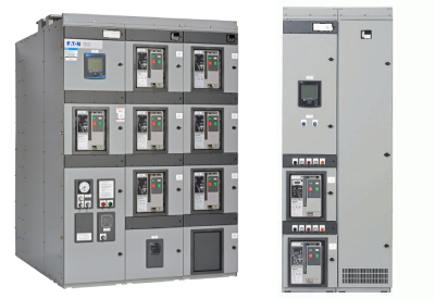
Low-voltage metal-enclosed switchgear is a three-phase power distribution product designed to safely, efficiently and reliably supply electric power at voltages up to 1,000 volts and current up to 6,000 amps. Typical ANSI/NEMA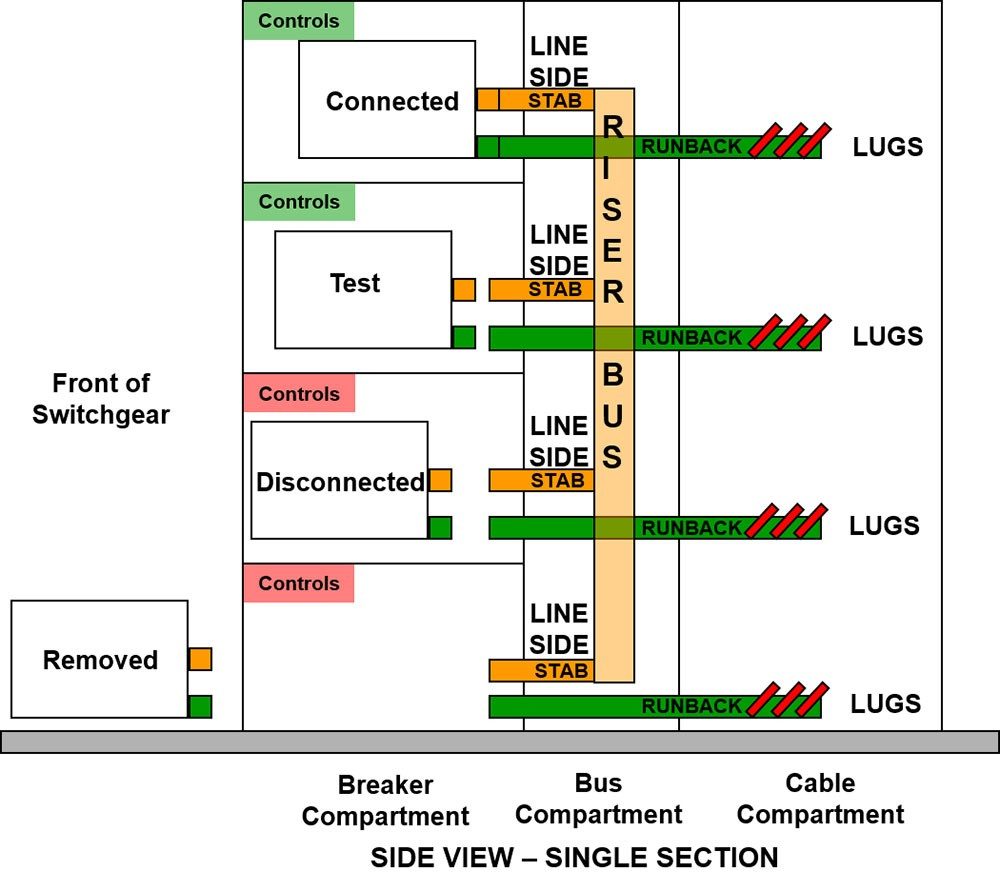 (American National Standards Institute, National Electrical Manufacturers Association) switchgear is rated for up to 635 volts with a continuous current main bus rating of up to 10,000 amps (for supplying power from parallel sources).
Low-voltage switchgear is often found on the secondary (low-voltage) side of a power distribution transformer. This transformer and switchgear combination is known as a substation. Low-voltage switchgear is typically used to feed low-voltage motor control centres (LV-MCC), low-voltage switchboards and other branch and feeder circuits. It is used to supply electricity for critical power and critical process applications such as those found in heavy industry, manufacturing, mining and metals, petrochemical, pulp and paper, utilities and water treatment, as well as in data centres and healthcare.
What are the main parts of low-voltage switchgear?
A typical structure or section of low-voltage switchgear consists of three distinct and segregated parts:
- Breaker compartment
- Bus compartment
- Cable compartment.
Each breaker compartment can normally hold up to four power circuit breakers arranged in a vertical fashion. Each power circuit breaker is individually compartmentalised from other breakers. Behind the circuit breaker compartment is the bus compartment which is also compartmentalised by solid barriers from the breaker compartment.
Adjacent bus compartments are segregated from each other by an insulated barrier between compartments. Finally, the cable compartment is at the rear of the switchgear section and it is optionally compartmentalised with vented or unvented barriers from the bus compartment.
The cable compartment has hinged doors or removeable covers that enable access to landing lugs for terminating line and load cables. This compartment arrangement is the most typical and may be called rear access switchgear, since access to the back of the switchgear enclosure is required.
A variation of this arrangement of compartments is front access switchgear where the cable compartment is adjacent to the breaker compartment, with the cable compartment doors located on the front of the equipment. This arrangement results in a much shallower design that requires no rear access and allows the switchgear to be placed up against a wall, similar to a switchboard
The extensive compartmentalisation of low-voltage switchgear is designed to increase the safety, reliability and serviceability of the switchgear by preventing, for example, accidental contact with certain conductors such as the main bus or circuit breakers in adjacent cells while performing maintenance. The compartmentalisation could also limit some of the damage from an arcing fault and reduce the risk of the fault propagating to other parts of the switchgear.
 Switchgear arrangement and power flow
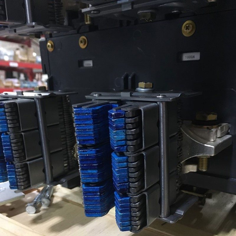
Power flows through the low-voltage switchgear enclosure via silver or tin-plated copper bus. Vertical sections (“risers”) of copper bus connect the breaker stabs which run horizontally into the breaker cells in a switchgear section and connect to the line sides of the feeder breakers via finger clusters. Horizontal (main) bus electrically connects adjacent switchgear sections to one another.
“Runbacks” run horizontally back from the load side of each feeder breaker, through the bus compartment (without connecting to the vertical or main bus) and into the cable compartment to provide lug landings for terminating load cables. In most cases, insulation or dielectric strength between the three bus phases is provided via an adequate air gap. In locations where bus clearances are not sufficient to provide the necessary dielectric strength, insulation is applied to the bus.
Low-voltage switchgear provides short-circuit and overload protection via low-voltage power circuit breakers (LV-PCB) with integral trip units. These low-voltage circuit breakers are typically through-the-door, drawout devices. “Through-the-door” means that the faceplate of the circuit breaker along with the breaker-mounted controls are accessible without opening the switchgear. “Drawout” means the circuit breaker can be easily moved into test and disconnect positions without opening the switchgear and can be fully withdrawn from the switchgear for service. Low-voltage circuit breakers interrupt short-circuit and overload faults via main contacts that part in open air. Consequently, such circuit breakers are also known as air circuit breakers (ACB) in contrast to medium voltage circuit breakers which typically use vacuum interrupters.
Low-voltage switchgear carries the following ratings:
Maximum voltage (typically up to 635V)
Power frequency (typically 50Hz and 60Hz)
Insulation level (typically 2.2kV)
Continuous current (typically up to 10,000A)
Short-circuit current tolerance (typically up to 200kA)
Short-time current tolerance (typically up to 100kA, 30 cycles)
There are several important standards that apply to low-voltage metal-enclosed switchgear which address the details of many of the points discussed above:
ANSI/IEEE C37.20.1, standard for metal-enclosed, low-voltage (1000 Vac and below, 3200 Vdc and below) power circuit breaker switchgear
ANSI/IEEE C37.20.7, guide for testing metal-enclosed switchgear rated up to 38 kV for internal arcing faults
UL 1558, metal-enclosed, low-voltage power circuit breaker switchgear
UL 1066, standard for low-voltage AC and DC power circuit breakers used in enclosures
What is short-circuit current tolerance rating?
The short-circuit current tolerance rating is also known as the short-circuit current rating (SCCR) of the switchgear. According to the ANSI/IEEE C37.20.1 standard, short-circuit current tolerance is defined as:
The designated limit of available (prospective) current at rated maximum voltage that it shall be required to withstand for a period of no less than four cycles on a 60 Hz basis under the prescribed test conditions. The rated short-circuit current tolerance determines the minimum bus bracing which is required of the design. The bus bracing may be able to withstand higher values than the stated rating.
In other words, the short-circuit current tolerance rating is the maximum short-circuit current that the switchgear assembly can safely withstand for at least four cycles when protected by an overcurrent protective device (OCPD). This rating will affect how the bus bar is mechanically braced to prevent bending and damage during a short-circuit event.
The purpose of this rating is to coordinate with the short-circuit current tolerance rating of the circuit breakers used in the switchgear. The short-circuit current tolerance rating of the switchgear must equal the short-circuit current tolerance rating of the lowest rated breaker used in the switchgear assembly. For example, if the main circuit breaker has a 100 kA short-circuit current tolerance rating but a feeder breaker has a 65 kA short-circuit current tolerance rating, the switchgear will carry a 65 kA rating.
What is interrupt rating?
Interrupt rating is a rating that applies to overcurrent protective devices such as low-voltage power circuit breakers. It is defined as the maximum current the overcurrent protective device is rated to safely interrupt at a specific voltage.
The interrupt rating of the circuit breaker must meet or exceed the short-circuit current tolerance rating of the circuit breaker. In some cases, the interrupt rating will exceed the short-time current (of the circuit breaker and the switchgear) resulting in a circuit breaker that will trip instantaneously (within 3–4 cycles), instead of with a short-time delay, in the presence of particularly high fault current.
Finally, the interrupt rating of the circuit breaker must meet or exceed the maximum available fault current that the upstream power source could supply in the event of a short-circuit fault.
What is short-time current tolerance rating?
According to the ANSI/IEEE C37.20.1 standard, short-time current tolerance is defined as: “The designated limit of available (prospective) current at which it shall be required to withstand its short-time current duty cycle (two periods of 0.5 s current flow, separated by a 15 s interval of zero current) at rated maximum voltage under the prescribed test conditions.”
In other words, this rating consists of two quantities: time (typically measured in cycles) and current (typically measured in kiloamps, kA). For low-voltage switchgear, the time rating is 30 cycles (0.5 seconds) and the current rating is the amount of short-circuit fault current that the mechanical assembly, electrical bus bar and bracing can endure for 30 cycles without sustaining damage at the tested voltage.
Low-voltage power circuit breakers also have a short-time current tolerance rating and the switchgear must equal the short-time current tolerance rating of the lowest rated breaker used in the switchgear assembly. For example, if the main circuit breaker has a 100 kA, 30 cycle short-time current tolerance rating but a feeder breaker has a 65 kA, 30 cycle short-time current tolerance rating, the switchgear will carry a 65 kA, 30 cycle rating.
Low-voltage power circuit breakers are specially designed to be able to withstand a fault of a given magnitude, without tripping, for up to 30 cycles. Compare this to moulded case circuit breakers (MCCB) which are designed to trip instantaneously (within 3–4 cycles) when subjected to fault current above the instantaneous setting. As a result, MCCBs are tested to withstand a short-circuit fault for only three cycles before tripping. The purpose of having circuit breakers and switchgear that can withstand a short-circuit fault for up to 30 cycles is to improve selective coordination.
What is selective coordination?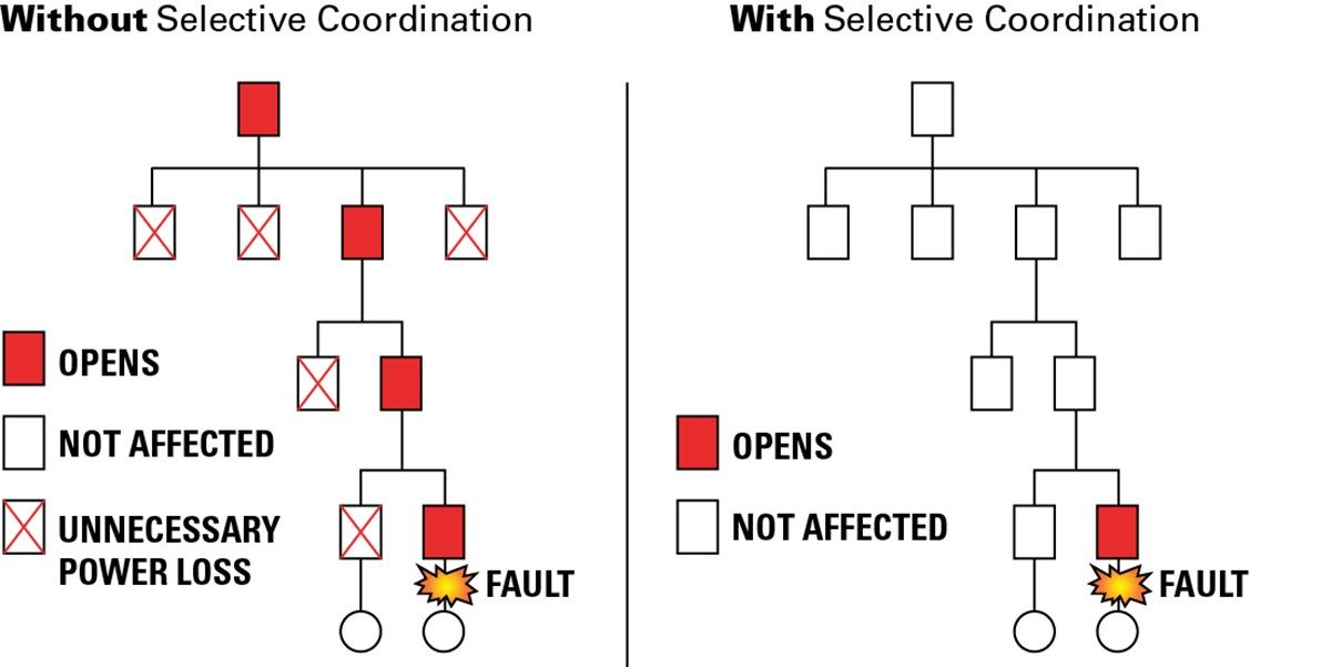
Selective coordination is achieved by setting the overcurrent devices in a system such that the device closest to the fault opens first, as opposed to all devices that see the fault current opening. Selective coordination applies for the full range of overcurrents on the system and the full range of interrupting durations associated with those overcurrents.
In other words, a short-circuit fault can occur downstream in a power distribution system, with upstream circuit breakers experiencing but withstanding the fault current and remaining closed while only the circuit breaker closest to the fault opens.
The purpose of selective coordination is to increase the reliability and uptime of a power distribution system. Theoretically, a relatively minor downstream fault in a system that is not selectively coordinated could result in multiple breakers tripping on overcurrent and causing widespread outage in the facility.
Such an outage could be catastrophic for emergency systems, life safety systems and other critical power applications. Consequently, the National Electric Code (NEC) devotes numerous articles to requirements around selective coordination for certain applications.
Such selective coordination is achieved with circuit breakers by modifying the instantaneous trip settings (if available) and short-time delay settings of the circuit breakers in the power distribution system. Even though moulded case circuit breakers may have electronic trip units with short-time delay settings, these devices are rated to interrupt maximum rated fault current within three cycles so only a limited amount of coordination can be achieved by adjusting the instantaneous trip levels for circuit breakers that are farther downstream and farther upstream. However, if a fault exceeds the instantaneous trip current of the breakers, the system is non-selective and a larger outage will occur.
Low-voltage power circuit breakers, on the other hand, have a short-time current tolerance rating which enables them to delay tripping for a preset time (up to 30 cycles). Consequently, a LV-PCB can be programmed to delay tripping in order to give downstream circuit breakers a chance to clear the fault first. Hence low-voltage switchgear with power circuit breakers can be used to greatly improve the reliability of a power distribution system. A properly coordinated system can also increase worker safety because the fault will be isolated downstream, reducing the likelihood that the worker will have to interface with upstream equipment which typically has a higher arc flash hazard.
Unfortunately, there is a downside to a power distribution system that has selective coordination implemented. Since moulded case circuit breaker instantaneous settings may be increased and power circuit breaker short-time delays programmed in order to achieve selective coordination, the incident energy at certain points of the system may increase. Incident energy is directly related to clearing time and available fault current (among other variables), so increasing the fault current or clearing time will result in increased incident energy. Therefore, it is even more important to follow the NEC Article 240.87 guidelines to reduce arc energy. Article 240.87 outlines several technologies that can be used to reduce the incident energy of power distribution equipment, some of which rely on reducing the instantaneous trip settings or overriding the programmed short-time delays in the event of an arcing fault.
What is the difference between switchgear and switchboards?
Low-voltage metal-enclosed switchgear and low-voltage switchboards are products used to safely distribute power throughout a facility. Both assemblies use free-standing enclosures that house circuit breakers, bus bar and power cables. Both products may contain meters, relays, potential transducers, current transducers and transfer schemes for redundant power. However, that is where the similarities end.
Switchboards are typically constructed with a dead-front, open-chassis design with few or no internal barriers between the cables, circuit breakers and bus bar. When the switchboard dead-front is removed, all bus bar, cables and terminations are exposed.
Switchboards are tested per the UL 891 switchboards standard and are normally composed of fixed-mounted moulded case circuit breakers which comply with the UL 489 MCCB standard. Switchboards tend to be front-accessible which means the incoming and outgoing cable terminations can be accessed from the front so the assembly can be mounted against a wall. These differences result in a smaller footprint than a similar switchgear assembly that contains the same number of circuit breakers.
Switchboards also tend to be less expensive than switchgear. For example, fixed-mounted MCCBs are less expensive than drawout power circuit breakers. However, MCCBs are not designed to be serviced and if the breakers are fix-mounted, the switchboard must be de-energised in order to replace them. Switchgear, on the other hand, contains drawout power circuit breakers which can be removed from the equipment while it is energised and are designed to be fully serviceable.
Switchboards only have a three cycle, short-time current tolerance rating versus a 30 cycle rating for switchgear. This is due to the fact that MCCBs also only have a three cycle short-time current tolerance rating. This means that achieving selective coordination is more difficult since short-time delays cannot be programmed in to provide time for circuit breakers farther downstream to clear faults.
Certain arc-flash safety technologies are also not available in switchboards. Such technologies available only in low-voltage switchgear include arc-quenching technology and arc-resistant construction.
In facilities that consume large amounts of power and facilities that require reliable power, switchgear and switchboards both play important roles. The switchgear may provide primary low-voltage power distribution and protection, often residing at the service entrance or on the secondary of a transformer substation, feeding power to various switchboards and low-voltage MCCs located throughout the facility which in turn feed smaller branch circuits such as lighting, HVAC and process-specific loads.